Physical Properties of Plastic Materials | The Complete Guide
The physical properties of any material or polymer are essential in determining its applicability and features. Let’s discuss the physical …
The physical properties of any material or polymer are essential in determining its applicability and features. Let’s discuss the physical …
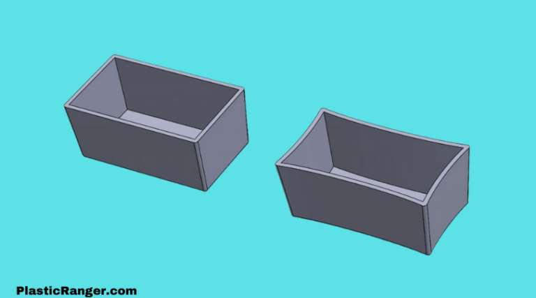
Warpage is a common and extremely stubborn problem to get rid of regularly seen in injection molded parts. Professionals working …
PVC manufacturers and suppliers can be found worldwide as PVC material is utilized everywhere for various applications. The main use, …
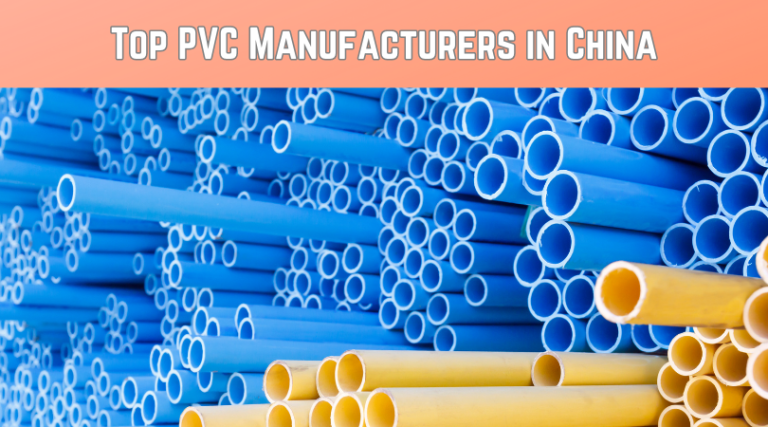
China’s PVC manufacturers are kind of a big deal in the global plastics scene. They’re not just making one or …
Greetings, everyone; I trust you’re all in good health and spirits. I’m thrilled to present a comprehensive comparison between PEX …